3.8 KiB
Executable File
3.8 KiB
Executable File
author, date, title, tags, uuid
| author | date | title | tags | uuid | |
|---|---|---|---|---|---|
| Akbar Rahman (20386125) | \today | MMME3085---Lab 1 Coursework |
|
864e5249-a02c-4896-b274-a0a76789955c |
\maketitle \newpage
Questions
Question 1
V_{ref} = 5V when converting the ADC-converted value because the ADC in the Arduino can read from 0 V to 5 V, thereforen_{ADC} = 0means the voltage to the pin is 0 V, andn_{ADC} = 1023means the voltage to the pin is 5 V- This is not the optimum use of the ADC pin as it means the resolution of the voltage measurement is less precise than it could be (roughly a resolution of 5 mV instead of 3 mV)
- The resolution could be increased by using an op-amp amplification circuit or a 3.3 V to 5 V level converter circuit
\newpage
Question 2
- 100 % duty cycle PWM is different from all the others as it is not a wave, but just a DC voltage
- Voltage is not zero in the OFF region because the rotational inertia is still spinning the motor, which creates a back EMF, and that is the voltage being read in the OFF region. Back EMF is proportional to the speed of the motor, which is why the voltage in the off region is higher when the PWM duty cycle, and therefore speed of the motor, is higher.

\newpage
Question 3
-
The difference between the ON+ and ON- is that the current will go in opposite directions, resulting in the motor spinning in opposite directions
-
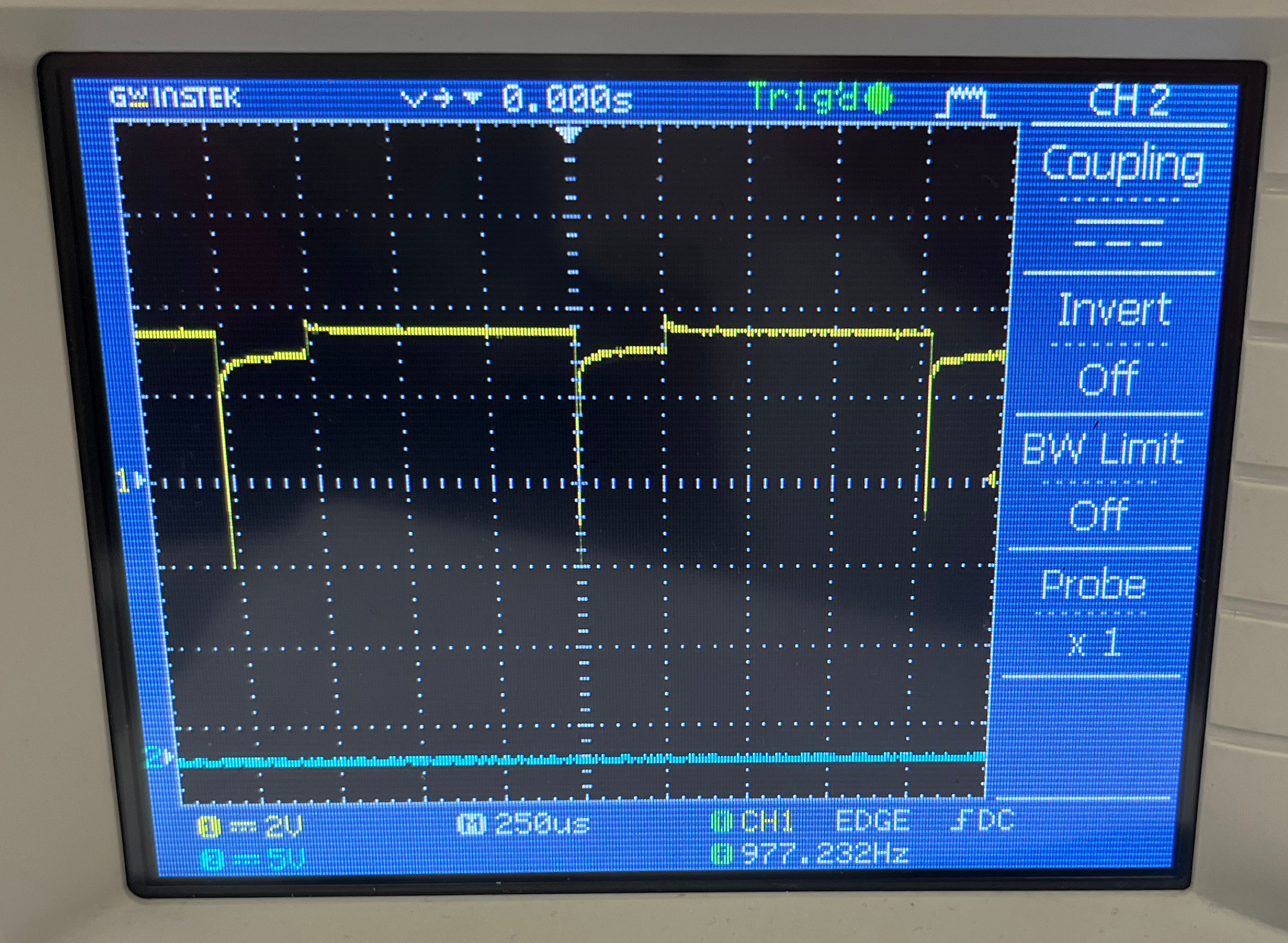
The default PWM frequency of pin 13 on the Arduino Mega 2560 is 976.5625 Hz 1
-
The audible frequency we hear is a ~1000 Hz square wave, which can be seen by the fact the period of the wave in figure below is roughly 1 millisecond

\newpage
Question 4
 { height=2in }
 { height=2in }
\newpage
Question 5
- Since the internal timer only looks at one edge of one pulse, it cannot be used to determine the direction of the rotation, which is one of the reasons to use a quadrature in the first place
- Therefore it is a viable alternative if you only care about the speed of rotation and direction is not important to the application
Question 6
- The main shortcoming observed is that the Arduino appeared to freeze/crash when entering a PWM duty cycle above ~20%
- When this issues occurs, the Arduino is too busy running the function called by interrupts to be able to print to serial, hence appearing to have frozen/crashed
- This is due to the fact that at higher speeds, the
updateEncoderStateMachine()function in triggered by the digital pin interrupts (which take higher priority) so frequently that theloop()function is not able to run, due to a lack of free CPU cycles, and therefore serial outputs are not printed and inputs not read - This effectively makes the counter useless as it cannot be read from as the Arduino is not able to handle any other processing tasks
- Additionally, there is a good chance that the Arduino is not able to run all the calls to
updateEncoderStateMachinein real time, and so the value ofcountwould be incorrect (of course this does not matter since we do not have the CPU cycles to do anything withcountanyway)
-
MotorEncoderAAR.inodefines that pin 13 is used for PWM output. Pin 13 is connected to timer 0 which defaults to 976.5625 Hz (https://playground.arduino.cc/Main/TimerPWMCheatsheet/) ↩︎