3.7 KiB
Executable File
| author | date | title | tags | uuid | lecture_slides | |||||
|---|---|---|---|---|---|---|---|---|---|---|
| Akbar Rahman | \today | MMME2051 // Introduction to Alternating Current (AC) |
|
0c90c691-cbf8-43e9-bfa5-7b277c853151 |
|
This section builds on complex numbers.
Sinusoidal Waves
This module will be using the following format:
y(t) = A\cos(\omega t + \Phi)where A is amplitude, \omega is frequency, \omega t + \Phi is phase angle, and \Phi is phase
offset.
Explore the effects of changing the variables in Desmos
Phasor
- a phasor is a complex number that represents the initial position of a rotating vector
- use the amplitude (
|V|) and phase offset (\Phi) of a cosine function - for all AC steady state analysis (
\omegais constant), these two variables are the only two needed
Example
For voltage v given by
v = 150 \cos (50t + 25)it may be represented in the phasor form
150 \angle 25Example
For current i given by
i = 10 \cos \left(50t -\frac{pi}{6}\right)it may be represented in the phasor form
10 \angle \frac{pi}{6}Phasors in Resistive Circuits
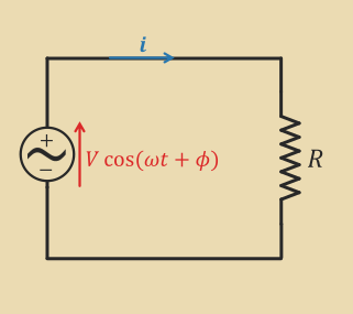
Convert all variables to phasors or to complex form
Apply KCL, KVL, Ohm's Law
\begin{align*} v &= iR \ V\angle \Phi = IR \angle\theta \ I \angle \theta = \frac VR \angle \Phi \end{align*}
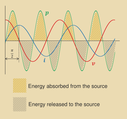
Phasors in Inductive Circuit
Ohm's law generalised to incorporate complex resistance, reactance, X:
\begin{align*} v &= iX \ V\angle\Phi_v &= I\angle\Phi_iX \ &= I\angle\Phi_ij\omega L \ \frac{V}{j\omega L}\angle\Phi_v &= I\angle\Phi_i\ \frac{{V}\omega L}\angle\left(\Phi_v - \frac{\pi}{2}\right) &= I\angle\Phi_i \end{align*}
Power
Resistive Circuits
P_\text{avg} = V_\text{rms}I_\text{rms}Inductive Circuits
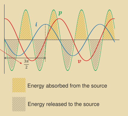
P = \frac{V^2}{2\omega L}\sin{2\omega t}Capacitive Circuits
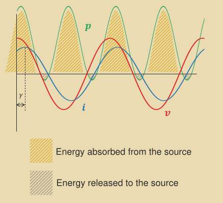
P = \frac{\omega CV^2}{2}\sin{2\omega t}Real Circuit (Resistive + Reactive)
P = V_\text{RMS}I_\text{RMS}(\cos \gamma + \cos{(2\omega t + \gamma)}P_\text{avg} = V_\text{RMS}I_\text{RMS}\cos \gammawhere \cos \gamma is the power factor (PF) and \gamma is phase deviation between voltage and current.
The PF tells us what fraction of the current does useful work.
Apparent, Active, and Reactive Power
Apparent Power:
S = V_\text{RMS}I_\text{RMS}- as power still flows losses still occur
- AC equipment is rated for apparent power as it handles both used and unused power
Active Power:
P = S\cos\gamma- this is the real power transferred to the load
Reactive Power:
P = S\sin\gammaResonance
The inductive load of on a circuit is Z_C = \frac{1}{j\omega L}.
If the frequency of the power supply matches \omega, you get resonance and the circuit becomes
purely resistive so there is a sharp drop in impedance.


