4.5 KiB
Executable File
| author | date | title | tags | uuid | lecture_notes | exercise_sheets | lecture_slides | |||||||||
|---|---|---|---|---|---|---|---|---|---|---|---|---|---|---|---|---|
| Akbar Rahman | \today | MMME2053 // Asymmetrical Beam Bending |
|
7afb5f13-4d55-4e00-927a-5d622520d844 |
|
|
|
Procedure for Solving for Bending Stress and Neutral Axis Position in Asymmetrical Bending Problems
- Determine the principal axes of the section (about which
I_{xy}= 0) - Resolve bending moments onto these axes
- Determine angle of neutral axis
- Evaluate bending stress at any position in the section, such as extremes away from neutral axis, which give maximum bending stress
Worked Example
- [Worked Example 1 (PDF)](./worked_examples/MMME2053 AB WE1 Slides.pdf)
- [Worked Example 2 (PDF)](./worked_examples/MMME2053 AB WE2 Slides.pdf)
Product Moments of Area
To analyse asymmetrically loaded sections, we need the second moments of area I_{yy}, and $I_{xx}$
but we also need I_{xy}, the product moment of area:
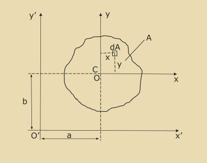
I_{xy} = \int_A xy \mathrm{d}AParallel Axis Theorem
The parallel axis theorem allows calculation of 2nd moments of area and product moments of area with
respect to x' and y' axes:
\begin{align*} I_{x'x'} &= \int_A y'^2 \mathrm{d}A \ &= \int_A (y+b)^2 \mathrm{d}A \ &= \int_A (y^2 + b^2 + 2by) \mathrm{d}A \ \ I_{x'x'} &= I_{xx} + Ab^2 \end{align*}
Similarly you can get
\begin{align*} I_{y'y'} &= I_{yy} + Aa^2 \ I_{x'y'} &= I_{xy} + abA \end{align*}
Principal Axes and Principal 2nd Moments of Area
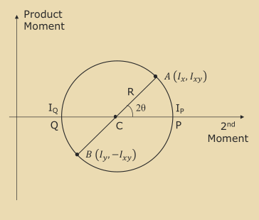
Once the second moments of area and product moments are found, they can be used to plot a Mohr's circle where:
-
Point A is plotted at
(I_{xx}, I_{xy}) -
Point B is plotted at
(I_{yy}, -I_{xy}) -
Points P and Q show the positions of the principal 2nd moments of area,
I_p, andI_q. -
\thetais the angular positioneof the principal axes with respect to the $x$-yaxesThe principal axes are the axes where the product moment of area is 0.
C = \frac{I_{xx} + I_{yy}}{2}R = \sqrt{\left(\frac{I_{xx}-I_{yy}}{2}\right)^2 + I_{xy}^2}I_p = C + RI_q = C - R\sin{2\theta} = \frac{I_{xy}}{R}Analyse Bending of a Beam with Asymmetric Section by Resolving Bending Moments onto Principal Axes
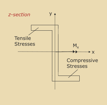
If a bending moment, M_x is applied about the x-axis only, then the stress in the flanges will
cause bending to takeplace about both x and y axes.
This is a consequence of I_{xy} \neq 0.
To avoid this moment coupling effect, it is usually convenient to solve bending problems by
considering bending about the principal axes, for which I_{xy} = 0.
Resolving onto Principal Axes
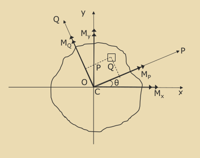
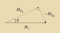
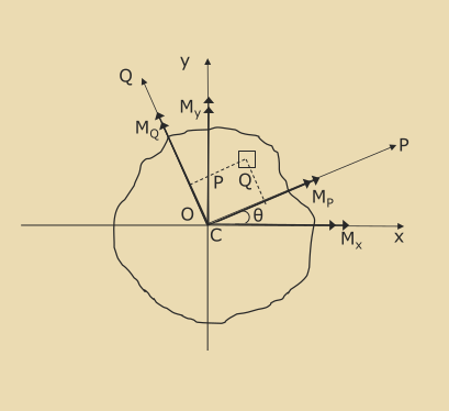
If bending moments M_x and M_y are applied about the x and y axes respectively, these can be
resolved onto the principal axes, P and Q:
\begin{align*} \cos\theta &= \frac{M_{P_x}}{M_x} \rightarrow M_{P_x} = M_x\cos\theta\ \sin\theta &= \frac{-M_{Q_x}}{M_x} \rightarrow M_{Q_x} = -M_x\sin\theta\ \end{align*}
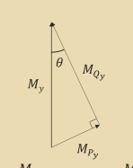
Similarly we get:
\begin{align*} M_{P_y} = M_y\sin\theta\ M_{Q_y} = M_y\cos\theta \end{align*}
Therefore:
\begin{align*} M_P = M_{P_x} + M_{P_y} = M_x\cos\theta + M_y\sin\theta \ M_Q = M_{Q_x} + M_{Q_y} = -M_x\sin\theta + M_y\cos\theta \end{align*}
Bending Stress at Position (P, Q)
\sigma = \frac{M_PQ}{I_P} - \frac{M_QP}{I_Q}Note the -ve sign, as a positive stress results in a -ve moment about the y-axis.
Position of the Neutral Axis
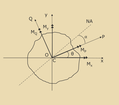
The neutral axis is where \sigma = 0:
\begin{align*} \frac{M_PQ}{I_P} &= \frac{M_QP}{I_Q} \ \frac Q P &= \frac{M_QI_P}{M_PI_Q} \ \ \alpha &= \arctan\frac{Q}{P} \end{align*}
The maximum stress is located in cross section point which is furthest from the neutral axis.
