2.0 KiB
Executable File
| author | date | title | tags | uuid | lecture_slides | lecture_notes | exercise_sheets | ||||
|---|---|---|---|---|---|---|---|---|---|---|---|
| Akbar Rahman | \today | MMME2051 // DC Motors |
|
b8313ef8-ef1e-486d-8031-52c39ac88751 |
|
|
Relevant lecture slides are 15-26. Two worked examples can be found in the lecture slides 24-26.
In a simple DC motor, the stator is either a permanent magnet or a coil with a current flowing through it. Both create a constant magnetic field.
The rotor is just a coil with current flowing through it by a (different) DC power supply:
Note the commutator and brushes. This flips the current direction inside the coil, flipping the direction of the induced magnetic field, and therefore flipping the direction of the resultant force.
The split in the commutator is placed such that the current flips just as the force would. This is visualised in this video (timestamped to 50s).
Torque, T
T = rBIl = KIusing F = BIl and T = rF, where B is magnetic field strength, I is current flowing through coil, l is length
of coil in the magnetic field,
K is a constant which varies with motor designs, and I is the current through the motor.
Back EMF, E_b
E_b = Bvl = K\omega where B is magnetic field strength, v is linear velocity, l is length of coil in field,
K is a constant defined by the motor, and \omega is angular velocity.
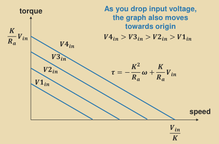
Relating Voltage to Motor Performance
There are two equations which govern the motor's performance:
V_\text{in} = E_b + IR\begin{equation} \label{eqn_torquespeed} V_\text{in} = K\omega + \frac{T}{K}R \end{equation}


