4.2 KiB
Executable File
| author | date | title | tags | uuid | lecture_slides | lecture_notes | exercise_sheets | |||||||||
|---|---|---|---|---|---|---|---|---|---|---|---|---|---|---|---|---|
| Akbar Rahman | \today | MMME2051 // Digital Electronics |
|
7d355a2f-68c7-4352-a164-7d51006ca137 |
|
|
Errata
Lecture Slides 5, p56
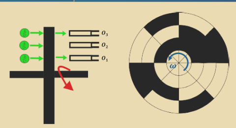
- The graph showing values of
O_1,O_2, andO_3are incorrect:
O_3should stay low throughoutO_2should stay low until after the fourth pulseO_1should be low until the third pulse, high between third and fourth, and then go back to low
- There is no mention that
O_4is the most significant bit andO_1the least.
Lecture Slides 5, p62-91
- The title should be Digital-to-Analog Converter (DAC)
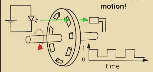
Shaft Encoder
A shaft encoder can provide angular position, angular speed, and direction.
Memory in Computers
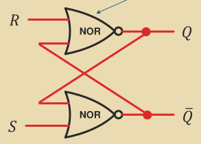
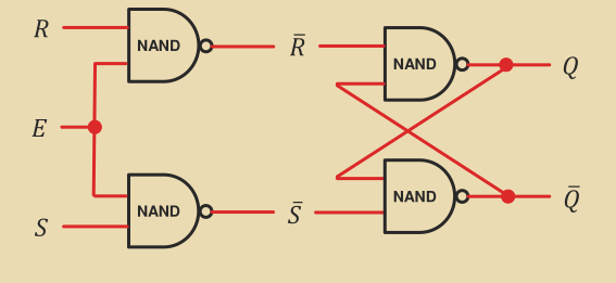
An OR gate can be used to create a latch which will stay high until it is reset:
Set/Reset Latch
An equivalent circuit can be built by replacing the NOR gates with NAND gates and taking NOTing the inputs before applying them (lecture 5 slides, p27).
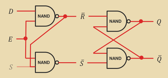
Enabling a Latch
Delay Gated Latch
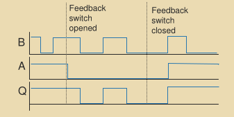
This latch allows memory to be set/reset without having a reset line.
Clock
A clock signal is a square waveform. The higher the frequency of the signal, the faster processing can happen. One step of processing is expected to happen per clock pulse. A clock pulse is usually considered to be its rising edge:
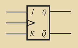
JK Flip-Flop
Flip-flops differ from latches mainly by the fact they are edge triggered (triggered by the edge of the clock pulse, rather than by change in input signals).
Q_\text{next} = J \bar Q + \bar K Q| Clock | J | K | Q_\text{next} |
\bar Q_\text{next} |
|---|---|---|---|---|
0 \rightarrow 1 |
0 | 0 | Q |
\bar Q |
0 \rightarrow 1 |
0 | 1 | 0 | 1 |
0 \rightarrow 1 |
1 | 0 | 1 | 0 |
0 \rightarrow 1 |
1 | 1 | \bar Q |
Q |
Serial to Parallel Conversion with JK Flip-Flops
There are errors in lecture slides relating to this section.
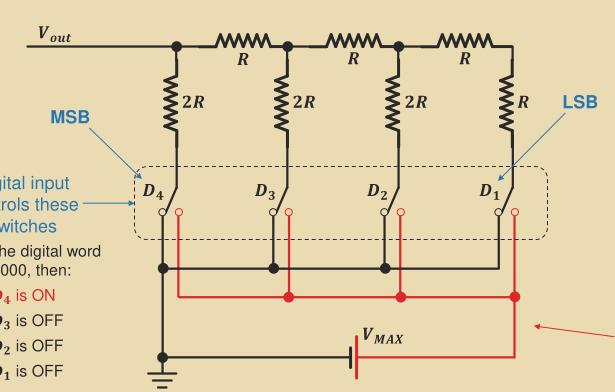
Digital to Analog Converter (DAC)
V_\text{out} can be expressed as the following:
V_\text{out} = \sum D_n\frac{1}{2^n}V_\text{max}where D_n is 1 for an high input and 0 for a low input.
The lecture slides go through the circuitry step by step (lecture 5, p62-91).
Comparator
If the positive input is larger than the negative, the output is high.
Analog Digital Converter (ADC)
Explanation in lecture slides (lecture 5, p93-94) and on flash converters (lecture 5, p95).
